
Trust Anchor Technical Support
![]() This is the technical support area for MULTOS Trust Anchor developer boards. These use high-security microcontrollers running the secure MULTOS operating system and can be used at the heart of embedded and IoT designs as the main microcontroller or as a supporting secure device.
This is the technical support area for MULTOS Trust Anchor developer boards. These use high-security microcontrollers running the secure MULTOS operating system and can be used at the heart of embedded and IoT designs as the main microcontroller or as a supporting secure device.
Solution integrators can develop specific customer applications to run securely in this environment and make use of pre-installed and third party functionality.
Software Installation
The SmartDeck SDK allows you to develop MULTOS applications in ‘C’, load them to your developer device, debug them (either in the chip or in a simulator) and finally build them for deployment on live products.
Watch the video to find out how to install and set up the software on Windows. Note this shows an old version of Eclipse being used. The latest installer will use Eclipse CDT 2018-12 or later.
The SmartDeck SDK and supporting Trust Anchor libraries can be downloaded from here. Please email dev.support@multos.com for an access code.


CREATING PROJECTS
The SmartDeck manual’s “Getting Started Guide” section describes how to create an Eclipse workspace and set up a new project. It is important to understand how a workspace and project is constructed. However, it is much faster to use the Tutorial’s workspace and make a copy of an existing project as a starting point for your own project.
EXAMPLE SOURCE CODE
Example source code can be found in the Tutorials section and covers:-
- Using GPIO pins
- Command mode
- Embedded mode
- Timers
- Communications using serial, i2c and SPI
- Sending APDU commands
- Fault handling
- Use of a WiFi module
- Performing application updates
SUPPORT
The MULTOS Application Developer Forum is the main place to ask questions and get support. If you would like to join the forum please contact us via the Developer Support contact form. There is also an FAQ.
WHAT CAN I USE A MULTOS TRUST ANCHOR FOR?
The MULTOS Trust Anchor is so much more than just a simple authentication device. It is a highly-secure general purpose microcontroller with proven protection against physical and logical attacks. It has hardware support for a wide range of cryptographic functions and so, depending on the use case, a MULTOS Trust Anchor can be used as a supporting trusted device in a larger system (essentially a mini Hardware Security Module or HSM) or as the master, controlling microcontroller in smaller devices. It also provides a contactless (NFC) interface opening up many more potential use cases.
HOW CAN A MULTOS TRUST ANCHOR BE USED?
A MULTOS Trust Anchor supports a number of modes making it very flexible.
- Command Mode: The device operates in command / response mode with commands sent on the serial port (or using I2C) being processed by the currently selected application. This is similar to how a smartcard works. The message protocols are defined here and here.
- Embedded Mode: The device runs an event handling loop. On detection of an event (for example a GPIO pin level change) applications that are registered to handle that event are called. MULTOS operates in this mode when it is powered up from an external power source.
- Smartcard Mode: The device operates through the smartcard interfaces it supports (Contact and/or Contactless) and is powered by those interfaces.
- Combined Mode: MULTOS operates in this mode when it is powered up from an external power source and energised by a contactless smartcard reader. When in this mode the GPIO, I2C, SPI and serial IO interfaces are also available so long as power is applied to the Vcc_GPIO pin.
CONNECTIVITY
The following connectivity options are supported:-
- GPIO: 12 GPIO pins arranged in two ports, a group of 8 (GPIO0-GPIO7) and a groupd of 4 (GPIO8-GPIO11). GPIO pins can be used individually or together as a port. Each group of 4 pins can source or sink a maxiumum of 4mA.
- Serial: Up to two serial ports can be configured, one on each GPIO port. In Command Mode, the default serial port is on pins GPIO10 (Tx) and GPIO11 (Rx). Speeds up to 57600 baud are supported.
- SPI (Master only): Supported on GPIO0 (MOSI), GPIO1 (MISO) and GPIO2 (CLK) with GPIO3-GPIO10 configurable as Slave Select (SS) pins.
- I2C (Master and Slave): Supported on GPIO8 (SCL) and GPIO9 (SDA)
See the Breakout Board details for more information.
DEBUGGING
GENERAL
Applications can be debugged in-chip using the Eclipse environment when using Command Mode. This is particularly useful when it is required to debug code that talks to external devices. Conditional compilation directives (#ifdef etc) can be used, if required, to allow applications that will eventually be run in Embedded Mode to be tested and debugged in Command Mode.
Note that the debugger needs exclusive access to the default serial port. It is therefore not possible to debug applications that make use of the default serial port. However, applications that make use of the secondary serial port can be debugged.
ENABLING IN-CHIP DEBUGGING
To put MULTOS into debugging mode when executing an application, the function miDebuggingEnable() must be called in the code. Execution will break at the statement following this call. IMPORTANT: In final builds of the application, any calls to miDebuggingEnable() must be removed or “compiled out” (through use of a #ifdef type mechanism).
ECLIPSE CONSIDERATIONS
Debugging an application in Eclipse for a MULTOS Trust Anchor is almost identical to debugging a MULTOS smartcard application. The only difference is that instead of a Windows simulator, hsim, being used, a communications interface program, mdi, is used instead. The change is made in the debugging command file. See the debugging.txt files in the eloyalty and led_flash tutorial projects.
Buy IoT Developer Kit
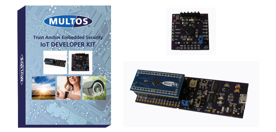
Available from DISTRELEC
click hereBuy Trust Core Developer Kit
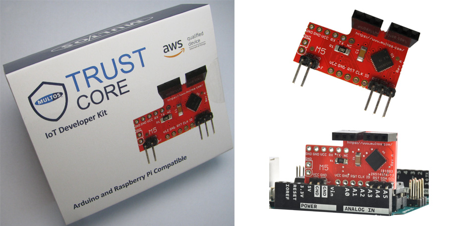
Available from Distrelec.
Click Here